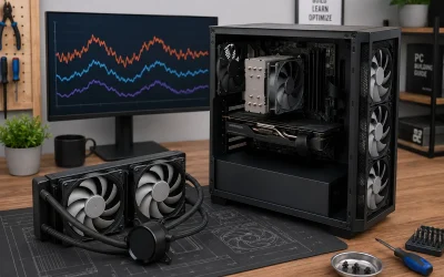
By the end of this guide you will have a closed-loop liquid cooler radiator securely mounted, fans oriented for optimal airflow, and coolant lines routed without kinks or strain. Your system will be ready to power on with controlled fan curves and no leaks or rattling. This walkthrough covers 120mm, 240mm, 280mm, 360mm, and 420mm AIO radiators in front, top, and side mount positions.
Prerequisites: You have already confirmed your case supports your radiator size by checking the manual or spec sheet, you have an AIO or custom loop radiator with included screws, and your motherboard has at least one available fan header and one AIO_PUMP or CPU_FAN header. Power off, switch off the PSU via the rear 0/1 switch, and unplug the AC power cord before starting.
Before You Start
| What you need | Why | Optional? |
|---|---|---|
| Radiator and fans with mounting screws (6-32 x 30mm for case/fan, M3 x 30mm or M3 x 35mm for radiator, plus short 6-32 x 5mm or M3 x 5mm if fans mount separately) | Long screws secure fan + case + radiator in one stack; short screws secure fan directly to case or radiator | No |
| Phillips #2 screwdriver, preferably magnetic | Prevents dropping screws into the case and stripping threads | No |
| Case manual or product page with radiator clearance and thickness limits | Confirms fit for radiator + fan stack, RAM and VRM heatsink clearance on top mount | No |
| Isopropyl alcohol 90%+ and lint-free cloth | Cleans old thermal paste if you are remounting the CPU block | Yes, if reusing cooler |
| Thermal paste (e.g., pea-sized 3-4mm dot) | Required if cold plate was removed or paste is compromised | Yes, if reusing cooler |
| Zip ties or Velcro straps and flush cutters | Secures tubes away from fans and provides strain relief | Yes |
| Flashlight or headlamp | Helps see mounting holes and threads inside dark cases | Yes |
| Small bowl or magnetic tray | Keeps screws organized by length and type | Yes |
Step-by-Step
Step 1: Choose Your Mount Location and Airflow Direction (5 minutes)
Inspect your case. Most cases list radiator support as Top: up to 360mm, Front: up to 360mm, Side/Bottom: up to 240mm. For the best CPU temperatures, front intake is usually ideal. For balanced GPU and CPU temperatures, top exhaust is preferred. Check the arrow icons molded on the fan frame. The open blade side is intake, the braced/spoke side with the sticker is exhaust. Decide now: front and side mounts should typically pull cool air in, top and rear mounts should push warm air out. If you are mounting in the front, tubes should ideally be at the bottom or side, not stretched taut over the GPU. If you are mounting on top, confirm at least 55mm of clearance above the motherboard for radiator + fan (30mm radiator + 25mm fan). Measure from the top rail to the tallest RAM stick or VRM heatsink.
Step 2: Prep the Case and Remove Obstructions (5-10 minutes)
Remove the relevant exterior panel: front panel pulls straight off via clips, top panel often slides back then lifts, side panel is held by two thumb screws or a latch at the rear. Remove any dust filters and set aside. Take out any pre-installed case fans where the radiator will go. Keep their screws labeled. If your case has a removable radiator bracket or tray, press the release tab and slide it out. This makes mounting far easier and is common in 2026 mid-tower designs with modular front and top rails. Lay the case on its side with the mounting area facing up so screws do not have to fight gravity.
Step 3: Attach Fans to the Radiator Correctly (10 minutes)
Place the radiator flat on a non-conductive surface with the ports facing toward you. Orient each fan so airflow goes in your chosen direction. For top exhaust, the sticker side of the fan should face up through the top of the case. For front intake, the open blade side should face outward through the front panel. Align the fan screw holes with the radiator holes. The radiator screw holes are threaded M3 on most AIOs. Use the correct long screws through the fan into the radiator. Tighten in a cross pattern: top-left, bottom-right, top-right, bottom-left, stopping when snug. Do not overtighten. Threads in aluminum radiator fins strip easily if you apply more than light fingertip pressure after contact. If your kit includes washers, place one under each screw head. Leave case-mounting holes empty for now unless your case requires fans screwed to the chassis first.
Step 4: Mount the Radiator and Fan Assembly to the Case (10-15 minutes)
Lift the combined assembly and position it against the mounting rails. The screw holes on the case are typically slotted to allow slight adjustment. Start all screws by hand two turns before tightening any of them to allow alignment. For top mount, you will usually drive four to eight 6-32 x 30mm screws from the top exterior through the case rail, through the fans, into the radiator. For front mount, drive screws from inside the case through the front rail into the fans and radiator, or from the front if a bracket is used then reinstall the bracket. On bracket-style cases, screw the radiator to the bracket first on a table, then slide the bracket back in until it clicks and secure the bracket thumb screws. After all screws are started, tighten in the same cross pattern until the assembly does not shift when you gently push it. There should be no bowing of the case rail and no fan frame deformation.
Step 5: Mount the CPU Block and Route Tubing (10 minutes)
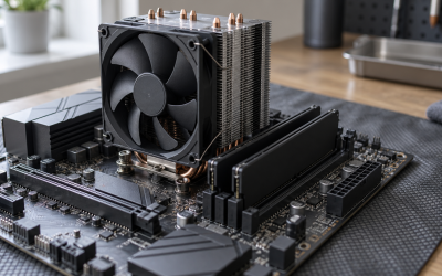
If your AIO block is not yet mounted, install the correct socket bracket. For Intel LGA1700/1800, use the rectangular backplate with adjustable studs. For AMD AM4/AM5, use the stock retention hooks with the clip or the included AM5 standoffs. Place the backplate behind the motherboard, insert standoffs through the board from the front, and secure. Apply thermal paste if needed, then seat the block. Tighten the block thumb nuts in an X pattern a half-turn at a time until finger-tight. Route the tubes so they have a gentle arc with no sharp kinks. Keep tubes away from fan blades and RAM. The tubes should not press against the GPU backplate. If excess length touches the GPU or rear fan, use a zip tie anchored to a case tie point to create a loose loop. Leave slack near the pump to prevent pulling on the CPU socket. Do not twist the fittings beyond their natural swivel.
Step 6: Connect Power, PWM, and RGB (5 minutes)
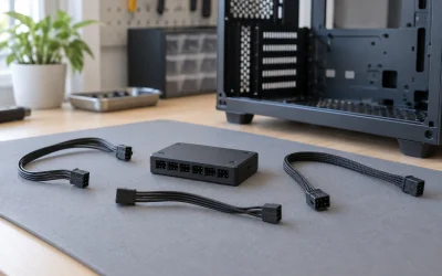
Route fan cables behind the radiator toward the nearest cable cutout. Connect radiator fans to a single header via the included splitter or daisy chain. Plug into CPU_FAN or CHA_FAN1. Connect the pump tach cable to AIO_PUMP or CPU_OPT. On most motherboards this header defaults to 100% duty. If you only have CPU_FAN and SYS_FAN, use CPU_FAN for the pump and CHA_FAN for radiator fans. For ARGB, connect the 3-pin 5V ARGB header labeled JARGB_V2_1, ADD_GEN2, or D_LED on ASUS, MSI, or Gigabyte boards. The 4-pin 12V RGB header labeled RGB_HEADER is not interchangeable. Secure loose cables with Velcro so they cannot contact fan blades.
Step 7: Configure Fan and Pump Control in Software (5 minutes)
Reconnect AC power, flip the PSU switch to 1, and power on. Enter BIOS by tapping Delete or F2 during boot. Navigate to the hardware monitor section. The exact path depends on vendor: ASUS path is BIOS > Advanced Mode (F7) > Monitor > Q-Fan Configuration; MSI path is BIOS > Hardware Monitor > Fan Control; Gigabyte path is BIOS > Smart Fan 6. Set the pump header to Full Speed or Manual at 100% duty (PWM value 255). Set radiator fan header to PWM Mode, curve based on CPU temperature, with points such as 30 percent at 30C, 50 percent at 55C, 75 percent at 70C, and 100 percent at 80C. Press F10 to Save and Exit. In Windows, install your cooler vendor utility if you want more granular curves. Location is typically C:\Program Files\VendorName\ or via Windows Settings > Apps > Installed apps. Set fan source to Coolant Temperature if the AIO reports it, otherwise keep CPU package temperature as source.
Verify It Worked
First, do a visual and audible check before booting to OS. With the system on, look at all fans through the panel. They should all spin without wobble or clicking. Listen for rattling that indicates a wire touching a blade. Check the pump RPM readout. In BIOS path Monitor > Fan Info or within HWInfo64 under Sensors > Pump, you should see a steady reading between 1800 and 3200 RPM depending on model. Zero or fluctuating RPM means the pump header is not set to 100 percent or is plugged into the wrong header.
Next, check temperatures and leaks. Boot to Windows, open Task Manager with Ctrl + Shift + Esc and then HWInfo64 or HWMonitor. Let the system idle for 10 minutes. Coolant temperature should settle and CPU idle should be stable without rapid spikes to 90C+ which suggests poor block contact. Run a light load such as Cinebench R23 single-core for 5 minutes and watch the fan RPM increase with temperature. Inspect all fitting points and the radiator seams with a flashlight for any moisture. Power off and gently rock the case side to side to listen for air bubbles rushing, which is normal initially but should diminish after a few minutes as air collects in the radiator end tank.
Finally, confirm airflow. Hold a thin tissue near the radiator exterior. For exhaust, it should be pushed away. For intake, it should be pulled toward the panel. Reinstall dust filters and panels. File locations for fan profiles if you need to back them up: ASUS Armoury Crate profiles at C:\ProgramData\ASUS\ARMOURY CRATE\Service\, MSI Center at C:\Program Files (x86)\MSI\MSI Center\, Gigabyte SIV at C:\Program Files\GIGABYTE\SIV\.
Mistakes to Avoid
Tubes Stretched Taut Over Components
What causes it: Choosing a mount that requires maximum tube length, such as top mount with ports at the far end from the CPU block, or rotating the block 180 degrees without slack.
How to check: With the side panel off, see if tubes pull tight when the case is moved or if they press hard against RAM or GPU. Try to slide a finger between tube and nearest component. If it does not fit, it is too tight.
What to do: Power off, loosen the radiator screws two turns, slide the radiator to the slotted position that gives the most slack, then retighten. Rotate the CPU block 90 degrees if the fittings allow, and re-route with a wider arc. Secure with a loose zip tie, not a tight bend.
How to undo: Return to the previous mount position and block orientation. Loosen block thumb nuts evenly, reposition, and retighten in an X pattern.
Fans Installed Backward Causing Negative or Choked Airflow
What causes it: Misreading the airflow arrows or assuming the sticker side is always intake. Mixing intake and exhaust fans on the same radiator.
How to check: Look at the arrow icons on the fan edge. Check BIOS fan speeds and run the tissue test. If temperatures rise immediately under load and air is being pulled in at the top when you expected exhaust, direction is wrong.
What to do: Power off and flip the entire fan assembly. Keep all fans on a single radiator moving air in the same direction. For case balance, aim for slightly positive pressure with one more intake than exhaust. Update the fan curve to match the new direction.
How to undo: Flip the fans back and restore the previous BIOS profile via BIOS > Tool > Save/Load Profile > Load from USB or Profile Slot 1.
Using Wrong Screw Length and Piercing the Radiator
What causes it: Using 6-32 x 30mm case screws directly into the radiator without a fan in between, or using universal screws that bottom out in the fin channel.
How to check: Compare screw length against the stack. The screw should engage 5 to 7mm of radiator thread. If a screw threads in more than 8mm without resistance, it is too long. Inspect for coolant smell or visible puncture between fins.
What to do: Stop immediately if you feel hard bottoming. Replace with correct short M3 x 5mm or 6-32 x 5mm screws for direct radiator mounting, or ensure long screws only pass through a 25mm thick fan first. If a puncture is suspected, do not power on. Remove the radiator and inspect under bright light.
How to undo: Back out the long screw, inspect the hole with a flashlight, and replace with the correct screw from the accessories box that came with the AIO. If coolant leaked, RMA the unit and clean the case with isopropyl alcohol.
Overtightened Mounting Pressure Warping the Case Rail or Stripping Threads
What causes it: Using a power driver or tightening screws sequentially around the edge instead of a cross pattern, which bows the rail and creates vibration noise.
How to check: Sight down the radiator. If the case rail is visibly bowed or fan blades scrape the frame, pressure is uneven. Try to wiggle each corner. One loose corner and one bowed corner indicates uneven torque.
What to do: Loosen all radiator screws three turns, then finger-tighten each in a cross pattern until each screw just makes contact plus a quarter turn. The radiator should be firm but not flexing the case. Add rubber fan gaskets if included to reduce vibration.
How to undo: Remove screws, verify threads are still intact by hand threading a screw without a fan, and remount using the correct pattern. If a thread is stripped, move to the next slotted hole or use a fan screw washer to bite a different section.
FAQ
Can I mount the radiator with tubes up or tubes down?
Both are functional if the pump is not the highest point in the loop. Tubes down at the front is technically best because air collects at the top of the radiator end tank away from the tubes. Tubes up is acceptable if you cannot route otherwise, as long as the top of the radiator is higher than the pump block. Avoid mounting the radiator flat on the bottom of the case with the block above it, as air will settle in the pump. If you hear gurgling after installation, tilt the case gently 20 to 30 degrees side to side while the pump runs at 100 percent to move trapped air to the radiator.
Do I need to remove the motherboard to mount the radiator?
Usually no. Front and side radiators can be installed with the motherboard in place, especially if your case has a removable bracket. Top mount may require extra clearance if your RAM is taller than 45mm or your VRM heatsink is bulky. Remove the top dust filter and try sliding the assembly in at an angle. Only remove the motherboard if you cannot access the pump backplate or if the top rail is blocked by the EPS 8-pin cable. In that case power off, disconnect 24-pin ATX and EPS cables, remove GPU, and unscrew the nine ATX standoff screws to lift the board.
Should radiator fans be intake or exhaust?
Use front and side radiators as intake to feed them the coolest outside air, and top radiators as exhaust to vent heat naturally. Push configuration (fans between case and radiator pushing air through) is simple and performs similarly to pull for most 27 to 30mm thick radiators. Pull (fans on the inner side pulling air through) makes dust cleaning easier without removing the radiator. Push/pull with fans on both sides improves airflow by a small margin but requires 55mm+ clearance and double the fan headers or a powered hub. Choose push or pull based on what gives you better tube clearance and easier cable routing.
How tight should the radiator and CPU block screws be?
Finger-tight plus a quarter turn is the target. For radiator screws, tighten until the fan frame is firmly compressed and the radiator does not shift. Do not use a drill driver above 3 Nm. For the CPU block, tighten thumb nuts in an X pattern gradually until they stop with moderate finger pressure. If you use a torque screwdriver, 0.5 to 0.6 Nm per nut is typical for AIO brackets. Check even contact by looking at thermal paste spread when you remove the block. It should be a thin, even rectangle covering the IHS. If paste is thicker on one side, loosen and retighten evenly.