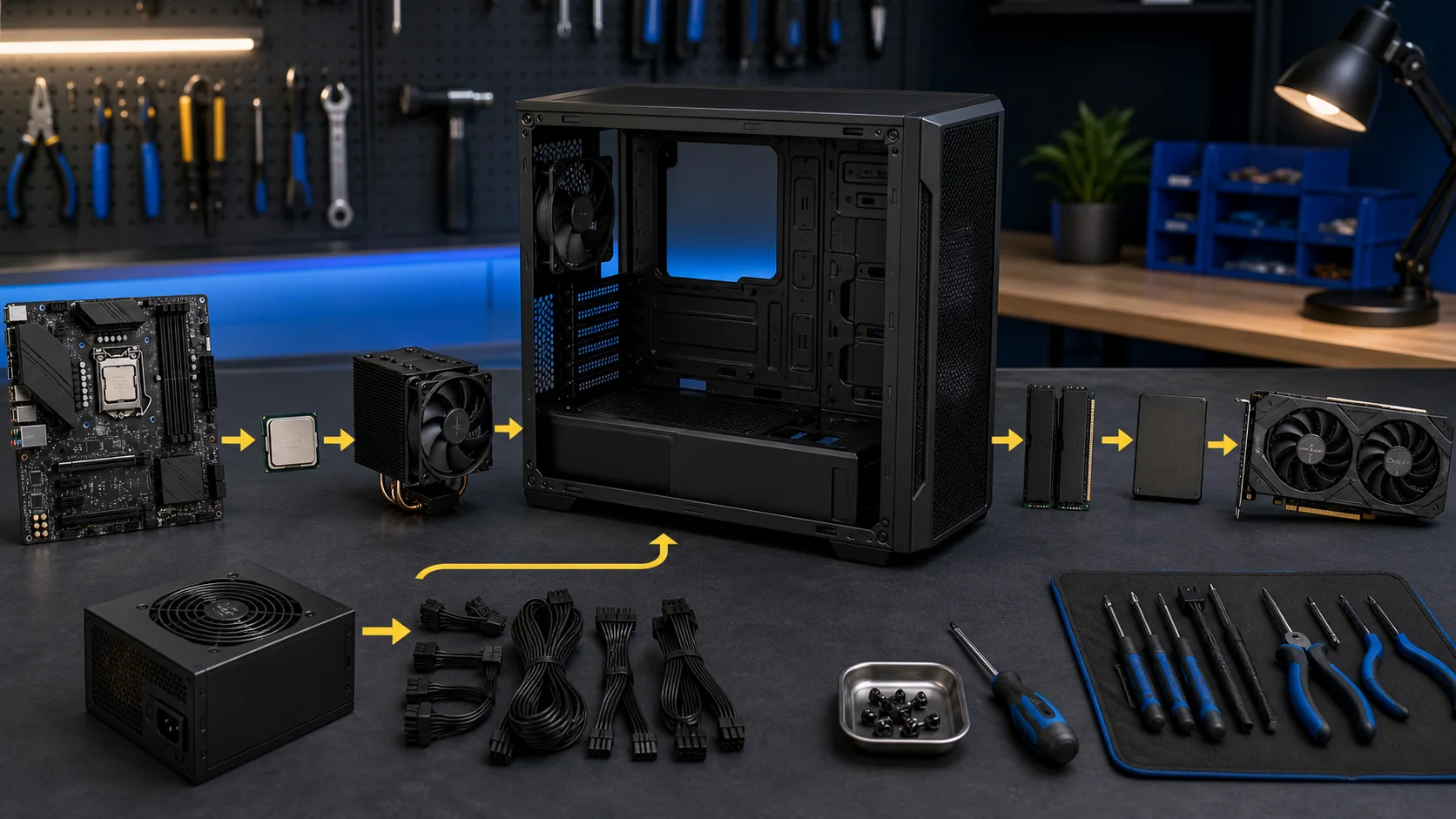
Building a gaming PC step by step means installing components in an order that avoids blocking access to earlier parts: CPU and cooler first, then RAM and M.2 storage, then the motherboard into the case, then power supply and cabling, and the graphics card last. Follow that sequence and a first build takes most people 3-5 hours; get it out of order and you’ll find yourself removing a GPU just to reach a RAM slot underneath it.
I’m Owen Pritchard, Technical Guides Editor here, and this sequence comes from years running an IT repair bench handling everything from dead PSUs to corrupted Windows installs, backed by a diagnostics bench with POST cards, spare parts for swap-testing and multiple OS images. The steps below are the same order I’d walk a bench customer through in person.
As an Amazon Associate we earn from qualifying purchases at no extra cost to you. Product prices and availability are accurate as of the date shown and are subject to change.



Top 3 picks at a glance
Gathering Tools and Prepping Your Workspace
You need less than most people assume: a Phillips #2 screwdriver covers nearly every screw in a modern build, a small parts tray or bowl keeps loose screws from rolling away, and a clean, hard, well-lit surface gives you room to lay out components before they go into the case.
An anti-static wrist strap, clipped to an unpainted metal part of your case chassis, removes the risk of a static discharge damaging a component during handling. It’s not mandatory if you regularly touch bare metal to ground yourself, but at under $10 it’s cheap insurance against a failure that isn’t always immediately obvious after the fact.
Unbox everything before starting and lay each component on its own anti-static bag or the box it shipped in, rather than stacking parts on top of each other. This single habit prevents the two most common workspace mistakes: losing a small screw pack, and setting a motherboard down on a surface that scratches its underside traces.
Keep your motherboard’s printed manual nearby rather than relying purely on memory or general knowledge — front panel header pinouts, RAM slot population order, and M.2 slot numbering vary enough between motherboard models that assuming a previous build’s layout applies here is a common source of avoidable mistakes.
For a build you’ll do more than once, a proper toolkit beyond a single screwdriver — precision bits, a magnetic parts tray, plastic spudgers for cable routing — pays for itself quickly. Our best tools for PC building guide and best anti-static wrist strap picks cover options at different budget levels.
Installing the CPU and Cooler
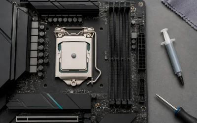
Install the CPU before the motherboard goes into the case — it’s far easier to see the socket clearly and apply even pressure on a flat surface than to do it once the board is mounted vertically inside a case with limited access angles.
Open the CPU socket’s retention arm, align the small gold triangle or notch on the CPU corner with the matching marker on the socket (both AMD and Intel sockets have this alignment indicator), and lower the CPU straight down without sliding it sideways. It should drop into place under its own weight with zero force required.
Close the retention arm to lock the CPU in place — you’ll feel and hear a distinct click as it seats. If it doesn’t close smoothly, don’t force it; that resistance almost always means the CPU isn’t seated correctly, and forcing the arm closed at that point risks bending socket pins on Intel boards or CPU pins on AMD boards.
Apply thermal paste if your cooler doesn’t come with pre-applied paste — a pea-sized dot in the center of the CPU’s heat spreader is enough, since the cooler’s mounting pressure spreads it evenly across the surface without you needing to manually spread it yourself.
Mount the cooler according to its specific bracket instructions, tightening mounting screws in a diagonal crisscross pattern rather than fully tightening one screw before moving to the next, which keeps even pressure across the CPU surface and avoids tilting the cooler’s contact with the heat spreader.
Installing RAM and M.2 Storage
Install RAM before the motherboard goes into the case for the same reason as the CPU — clear access and better visibility make it faster and lower-risk than reaching around a case’s front panel or a nearby fan once everything is mounted.
Check your motherboard manual for the correct slot population order for dual-channel operation — most boards want two matched sticks in slots 2 and 4 (counting from the CPU) rather than 1 and 2, and getting this wrong doesn’t break anything, but it does leave real performance on the table by running in single-channel mode instead of dual-channel.
RAM slots have a keyed notch that only lines up one way, and each slot has a lever on one or both ends that you push open before inserting the stick. Press down firmly and evenly on both ends of the stick until the levers snap closed on their own — a stick that’s only seated on one side won’t register in POST.
M.2 NVMe SSDs install into a small horizontal slot on the motherboard, secured either by a tiny screw or a tool-free latch on newer boards. Insert the drive at roughly a 30-degree angle into the slot, then press it flat and secure it, matching the standoff screw position to the drive’s physical length (2280, 2260, or 2242, printed on the drive itself).
Many current motherboards include a heatsink cover over the primary M.2 slot — remove it before installing the drive, then reattach it afterward, since running an NVMe drive without its heatsink under sustained load can lead to thermal throttling that reduces sustained read and write speeds.
Mounting the Motherboard in the Case
Before mounting the motherboard, confirm your case has the correct standoffs installed for your board’s form factor (ATX, Micro-ATX, or Mini-ITX) — most cases ship with universal standoff mounting points, but not every position needs a standoff for every board size, and an extra standoff under a spot with no matching screw hole can short the board.
Install the I/O shield first if it’s a separate piece rather than pre-attached to the board — it snaps into the rectangular cutout at the back of the case from the inside, and it’s much easier to seat correctly before the motherboard is in the way, since you’ll need both hands and clear sightlines to align all the small tabs.
Lower the motherboard into the case at a slight angle, aligning the rear I/O ports with the shield’s cutouts first, then lowering the rest of the board down onto the standoffs. Confirm every screw hole lines up with a standoff before starting to drive any screws.
Secure the board with the screws provided by the case, starting near the center and working outward in a criss-cross pattern similar to CPU cooler mounting, snugging each screw rather than fully tightening it until all are started, which avoids warping the board slightly out of flat alignment.
Double-check that the board sits flush against every standoff with no visible gap or tilt before moving on — a board that’s slightly bowed from an uneven mount can cause intermittent contact issues with RAM or expansion cards that are frustrating to diagnose later.
Installing the Power Supply and Routing Cables
Mount the PSU with its fan facing whichever direction matches your case’s ventilation design — most tower cases expect the fan facing down toward a bottom vent, drawing in cool air from outside the case rather than recycling warm interior air, though some smaller cases route it differently, so check your case manual.
For a modular or semi-modular PSU, attach only the cables you actually need before mounting it in the case — the 24-pin motherboard cable, CPU power (4+4 or 8-pin), PCIe power for the GPU, and SATA or peripheral power as needed. Leaving unused cables detached keeps the case interior meaningfully cleaner.
Route the 24-pin and CPU power cables through the case’s dedicated cable-routing cutouts on the back side of the motherboard tray rather than across the front of the board, keeping the main airflow path clear and making the finished build look noticeably tidier.
Connect the 24-pin cable to the motherboard first, since it’s usually the hardest to reach once other cables and the GPU are in place, followed by the 4+4 or 8-pin CPU power connector near the top of the board, which powers the CPU specifically and is separate from the main 24-pin.
Zip-tie or use the case’s built-in cable management straps to bundle excess cable length on the back side of the tray. This isn’t purely cosmetic — bundled, organized cables improve airflow slightly and make future upgrades or troubleshooting far easier since you can trace a specific cable without digging through a tangle. Our best cable management accessories guide covers ties, combs and routing channels worth adding.
Installing the Graphics Card
Install the GPU last among major components, since its size and position typically blocks easy access to nearby RAM slots and sometimes the CPU power connector, both of which you want fully finished before the card goes in.
Locate the primary PCIe x16 slot, usually the top full-length slot closest to the CPU, and remove the matching expansion slot covers on the back of the case — most modern GPUs occupy two to three slot widths, so check your specific card’s thickness before removing covers.
Open the slot’s retention latch, align the card’s gold PCIe connector with the slot, and press down firmly and evenly until it clicks into place and sits flush against the slot. You should feel a distinct click from the retention latch confirming a full seat.
Secure the card’s bracket to the case with screws through the expansion slot covers you removed, then connect the required PCIe power cables from your PSU — most current mid-range and high-end cards need one or two 8-pin connectors, or the newer 12VHPWR connector on recent Nvidia cards, and running a card without adequate power connected is a common cause of a system that boots but shows no display.
Support brackets or anti-sag brace kits are worth adding for larger, heavier cards, since GPU sag over time can stress the PCIe slot’s solder joints and, in extreme cases, cause intermittent connection issues — a support bracket is inexpensive and prevents this proactively rather than after the fact.
Connecting Front Panel and Case Headers
The front panel connector — a small block of individually labeled pins for the power switch, reset switch, power LED, and HDD activity LED — is the single most common point of confusion in a first build, since the pins are tiny, unlabeled clearly on some boards, and easy to misplace.
Consult your motherboard’s manual for the exact pin diagram rather than guessing from memory, since layout varies between manufacturers. Most boards label pins directly on the board itself in small print, though it can require a flashlight and close inspection to read clearly.
Polarity matters for the LED pins (positive and negative) but not for the power and reset switch pins, which are simple momentary contacts — if an LED doesn’t light up after first boot, try reversing that specific 2-pin connector rather than assuming a bigger problem, since a reversed LED connector is harmless and simply won’t illuminate until flipped.
Front panel USB and audio headers use larger, distinctly shaped connectors that are generally keyed to prevent incorrect installation, making them lower-risk than the small individual front panel switch pins, but still worth double-checking against the manual since a connector forced in upside-down on a non-keyed header can bend pins.
Case fan headers, distinct from the front panel switch block, connect to labeled SYS_FAN or CHA_FAN headers around the board — connecting case fans to these rather than daisy-chaining them all to a single header lets your motherboard’s fan curve control each one, or each group, independently based on temperature.
First Boot and BIOS Configuration
Before closing the case, do a first boot with the side panel off, which lets you visually confirm fans are spinning and quickly access components if something needs adjustment, rather than discovering an issue after fully closing everything up.
Connect a monitor to the GPU’s output, not the motherboard’s onboard video output, since most gaming builds with a discrete GPU won’t display anything through the motherboard’s own ports once a card is installed, and plugging into the wrong output is a common source of a false “no display” scare.
Press the power button and confirm fans spin, RGB lighting activates if present, and you reach either a BIOS/UEFI splash screen or POST beep code. A single short beep on systems with a speaker installed generally indicates a successful POST with no detected errors.
Enter the BIOS (usually by pressing Delete or F2 repeatedly during boot) and confirm the system recognizes your full installed RAM capacity and correct CPU model, then enable XMP or EXPO memory profiles, which run your RAM at its rated speed rather than a conservative default — this is a commonly missed step that leaves noticeable performance on the table.
Set your boot drive priority to the SSD or drive you intend to install an OS on, save BIOS settings, and proceed to Windows installation, covered in more detail in our how to install Windows on a new PC guide.
Troubleshooting No Post or No Display
If the system powers on (fans spin, lights come on) but shows nothing on screen, first confirm the monitor cable is connected to the GPU’s output port, not the motherboard’s — this single mix-up accounts for a large share of “dead PC” reports that turn out to be a fully working system.
Reseat the RAM sticks one at a time, trying a single stick in different slots if you have more than one, since a RAM seating issue is one of the most common causes of a no-POST condition, and it’s usually solvable in under two minutes without any other troubleshooting.
Check that both the 24-pin motherboard power and the CPU’s separate 4+4 or 8-pin power connector are fully seated — a connector that looks plugged in but isn’t fully clicked into place is a surprisingly common cause of a system that seems to power on (fans spin briefly) but doesn’t actually POST.
Reseat the GPU firmly, confirming the PCIe power cables are connected, and try a different PCIe power cable from the PSU if your unit is modular, since a specific cable can occasionally be faulty even when everything appears correctly connected.
A motherboard with a built-in diagnostic LED display or debug LEDs (present on many mid-range and higher boards) will show a specific code or light up a specific colored LED — CPU, RAM, GPU, or Boot — indicating which stage failed, and checking your manual against that code narrows troubleshooting dramatically compared to guessing. For a bench-quality diagnostic setup that catches these issues faster, our best diagnostic tools for gaming PC guide covers POST card and multimeter options.
Moving to a new build usually means retiring the old drive, and save data tucked away in AppData or a game’s install folder is easy to forget in the process — our save backup checklist walks through finding those folders before you power down the old rig.
Frequently asked questions
What order should I install gaming PC parts in?
CPU and cooler first, then RAM and M.2 storage, all while the motherboard is out of the case on its box. Only after that do you mount the motherboard, install the PSU, route cables, then seat the GPU last, since it blocks access to nearby components once installed.
Do I need an anti-static wrist strap to build a PC?
It’s not strictly required if you regularly touch a grounded metal surface like your case chassis, but a wrist strap removes the risk entirely for a few dollars. Static discharge damage isn’t always immediately obvious, so it’s cheap insurance rather than a mandatory step.
How long does building a gaming PC take for a first-timer?
Budget 3-5 hours for a first build, including careful cable management, versus 1-2 hours for someone experienced. Rushing the CPU socket and GPU seating steps specifically is where most costly mistakes happen, so slow down at those two points even if you speed through the rest.
What if my new PC doesn’t turn on at all?
Check the front panel connector pins first, since a reversed or misplaced power switch header is the single most common reason a fully assembled PC won’t turn on. Next check that the 24-pin and 8-pin CPU power cables are fully seated, since a partially inserted connector can look connected but isn’t.
Can I build a gaming PC without any prior experience?
Yes, modern components use keyed connectors that only fit one way, which prevents most catastrophic mistakes. Going slowly, reading each component’s manual for its specific socket or slot details, and not forcing anything that doesn’t slide in easily will get a first-timer through safely.